I’ve been doing a lot of projects in the physical, non-code world lately, especially with 3D printing. It’s gotten to the point where any time I encounter a problem, my first thought is “How can I 3D print my way out of this?” As a result, I’m constantly reaching for my trusty metal electronic calipers and measuring things, then grabbing my iPad and sketching out some ideas.
This is all great fun, but it leaves me feeling naked and vulnerable when I’m out of the house and I don’t have my calipers. I never got into the purse habit, and you can’t just pop a set of full size calipers in your pocket. I mean I guess you could. It sounds uncomfortable.
I particularly feel this need at the hardware store. Items are often customer-shelved, the labels are often badly scratched, and it’s sometimes faster to just take a quick measurement than to try to find and read the official number.
So the thought struck me recently that a small set of calipers on a keychain would be super useful. I went on Amazon, and found a bunch of listings for cheap little metal calipers. Unfortunately, I ordered some, and immediately found that they’re basically toys. They’re offset by over a millimeter, and the markings aren’t quite a millimeter apart even after you account for the offset, which makes them pretty useless, since they only measure a range of 0-30 millimeters in the first place. And once I had them in my hand, it was clear that a keychain that looks like a tiny scale model of a set of calipers is silly. All of the keychains I found were like this: more of a cheap novelty than something intended to be useful.
I also realized that a functional calipers keychain doesn’t need to be that small. People regularly carry around things like access cards on their keychains, and those are reasonably comfortable to keep in your front pocket.
So I designed and made my own. But I found that there were some interesting constraints to making a useful set of calipers this compact. If you just want to make your own, you can skip to the “Assembly” section below, which includes CAD files. You’ll probably want to at least read the next section though.
Usage
Before I get into how I designed this and how they work, let’s look at how you actually read them.
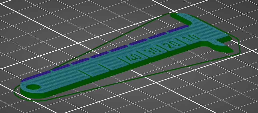
These calipers have a range of about 49 millimeters, and are read in two steps. First, you read the tens off the main scale. You’re looking at whichever section is fully revealed, so if you see most of the twenty, you’re still at 10.
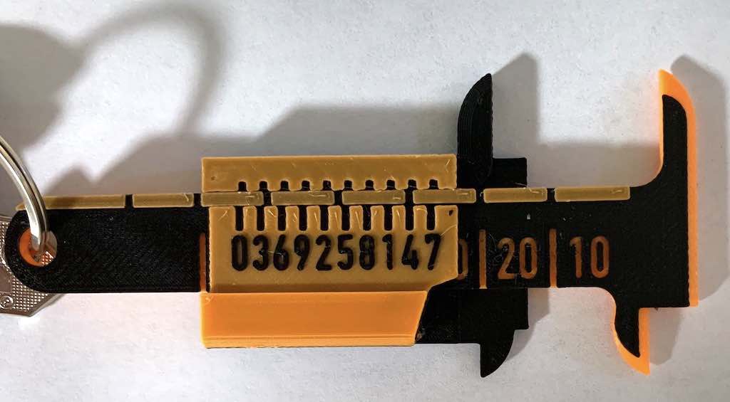
Next, look at the slider, and see which marking best lines up with a marking on the rail. If that marking is on the side with the digits, then your ones digit is that number. For example, this is what 24 mm looks like:
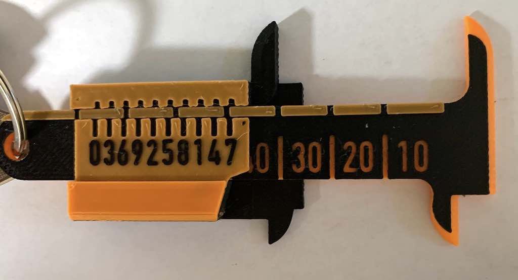
If the best aligned marking is across the rail, then add 0.5mm to the digit across from it. So this is what 36.5 mm looks like:
If the best aligned marking is a little bit off, you’ll probably find that there are two markings that kind of match. The measurement will be somewhere in between those. I’ll tend to vaguely guess at around quarter millimeter increments in these cases, but don’t expect to get too much precision. These are plastic, 3D printed calipers, so they’re a little flexible, and they’re not designed to ultra-tight tolerances. Good enough to sketch something out and refine it later, but not a substitute for a good set of calipers.
Features
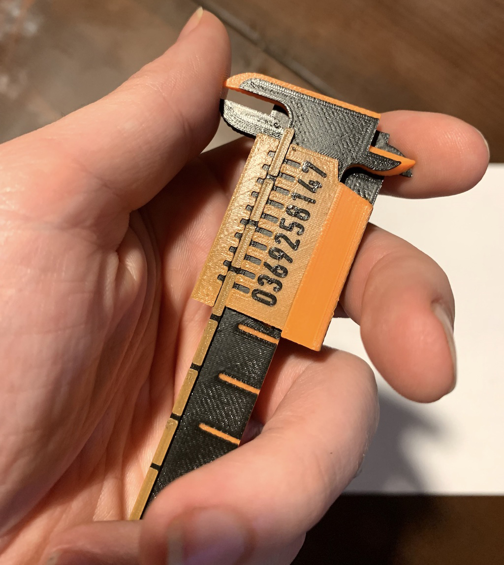
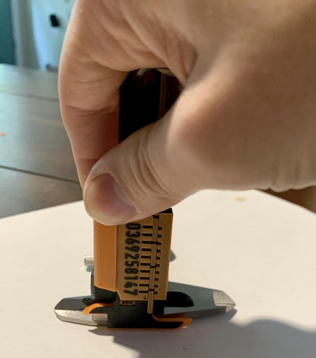
In addition to the well-known inner and outer jaws, you can also use these calipers to measure height (a pretty typical, but slightly lesser known feature of many calipers). Here they are measuring the height of my digital calipers:
Design
So why did I design them this way, rather than just putting millimeter markings on the body? Well, for one thing, it’s hard to emboss very fine marks like that with filament printing. I also find reading old-school calipers at millimeter precision pretty slow and annoying. You really have to get in there to see which marking you’ve hit. I also didn’t want to try to build a retainer into these to lock in a measurement, which means you really need to be able to read them in place, which makes it even more awkward to look closely at the main scale.
Of course, electronic calipers solve this by just giving you a nice big display of numbers. I almost never bother with the retaining screw on electronic calipers, because I can see the measurement immediately. I wanted to find a way to get that kind of magnified display on my keychain calipers.
Here’s the thing: traditional calipers already have a system for magnifying a measurement. It’s called a “vernier”.
Verniers
A vernier is a visual aid included on many mechanical instruments to exploit the human visual system to make it easier to take precise measurements. It takes advantage of a quirk of vision, where markings that line up tend to jump out at us.
Let’s look at how verniers work. Most of the explanations I’ve found online just give some examples, and don’t really go into why they work.
Typically, a vernier is used on a set of calipers to allow submillimeter precision, but let’s look at what a traditional vernier that deals in millimeters would look like.
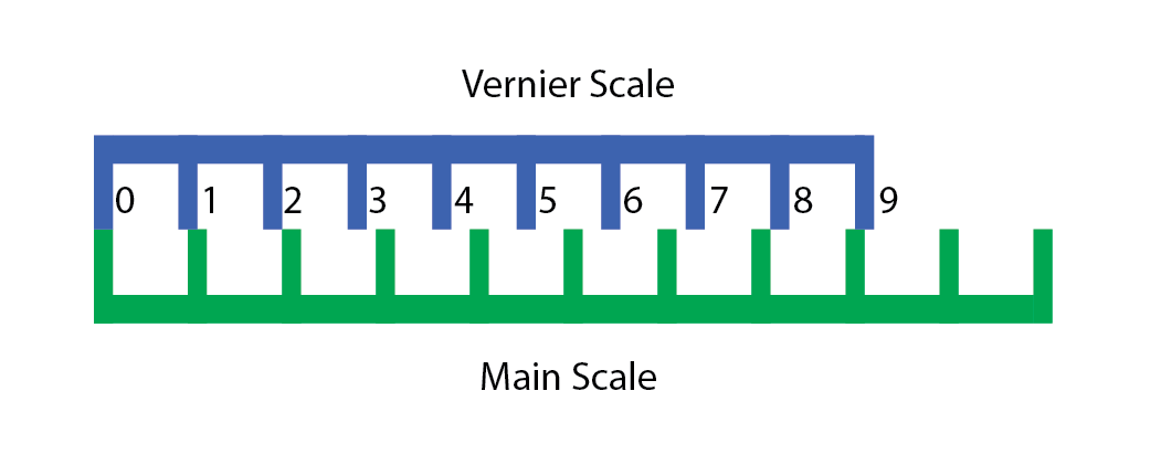
A vernier uses two scales, the main scale, and the vernier scale. These scales have their markings placed at different intervals. In our 1 mm vernier, the main scale has its markings at 10 mm, while the vernier scale has its markings at 9 mm.
We can see now, that if we shift the vernier right up by 4 mm, like so…
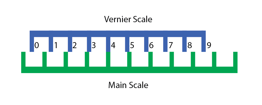
the “4” marking on the vernier scale lines up with one of the markings on the main scale.
The reason is because of remainders. Each marking on the vernier scale “loses” a millimeter compared to the main scale, so for the v-th Vernier marking to line up with any marking on the main scale, it must be moved right by v millimeters (mod 10).
OK, but your vernier doesn’t look anything like that
Yeah, so the problem with using a traditional 1-mm scale vernier is that it would have to be 9 cm long. And the size of the slider is wasted range. If both the slider and the body are 9 cm, you can’t measure anything at all, and then the jaws also take up space. So to make my calipers useful, they’d need to be about 15 cm long, which is not convenient to fit in your pocket.
But the vernier is all about modular arithmetic. We don’t care which marking on the main scale our vernier marking lines up with. We just care that we hit a marking when measuring the corresponding distance.
So what if we chop up our vernier scale into three pieces like this?
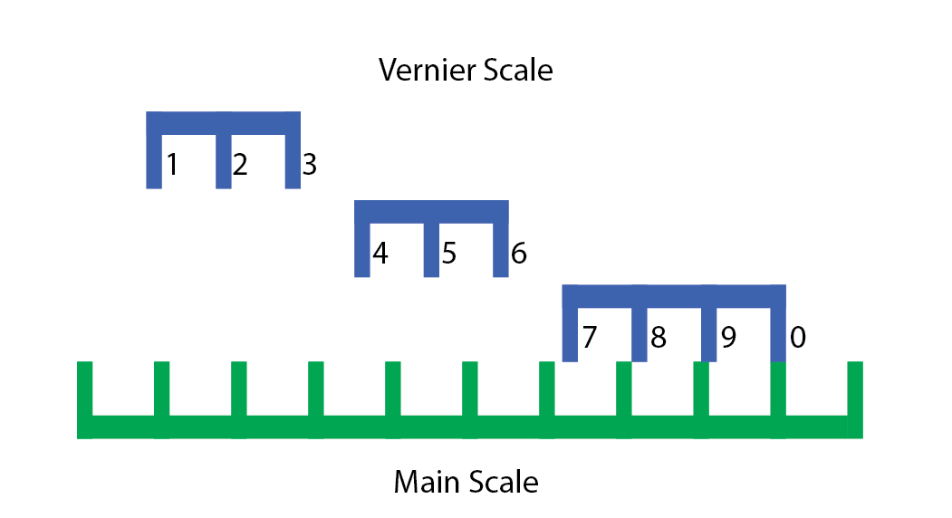
Now we can move these pieces wherever we want, and as long as we stick to a multiple of 10 mm, the vernier will still work. So we shift them over to all fit within the same 3 cm range. This is easiest to demonstrate with an interactive demo:
Move the slider to shift the verniers along the main scale. The “normal” vernier scale is directly above the main scale, with the chopped up verniers above. When a vernier marking lines up with a main scale marking, both are highlighted.
Notice that if you read the numbers on the chopped scales from left to right, they’re in the same order as they appear on my vernier. I’ve taken these three vernier scale segments, and overlaid them to fit within a smaller range.
I’m guessing I’m not the first to invent this kind of “chopped up” vernier scale, but I couldn’t find any prior art for it. I’d bet that a description of something very similar to this is sitting in some forgotten 80-year-old book on nomography in a library somewhere.
What’s nice about this approach is that it lets you tune the size of your slider to trade off readability against space, which is exactly the sort of control you need if you’re trying to build a usable set of calipers you can keep in your pocket.
And what about the 0.5 markings?
There’s nothing particularly special going on with the half-markings. They’re just shifted by 0.5 mm. It’s just a separate vernier scale with an offset. The reason I’ve included them is that the vernier effect works best when there’s a really unambiguous alignment, so the half-markings ensure that there’s always a close match.
Enough about the verniers, what is going on with that faceplate design?
I went through several iterations on the slider. My initial design had it as a single print with supports, but it’s very difficult to get it to both fit snugly, and run smoothly along the body that way. It’s also horrible to try to get support material out of that part.
The slot-and-rail design is set up to keep the vernier system as flat as possible. The more inset those markings are, the more you have to look head-on to get a good reading, which is inconvenient.
If you can print soluble supports, you might want to redesign the slider to print as a single piece, since inserting the faceplate during the slider print is the most likely step to fail.
Assembly
OK, enough talk about how and why they’re designed like this. Let’s talk about how to make your own.
You’ll need the CAD files, which you can get here.
I’ve included SHAPR and STEP files if you want to make modifications, and the 3MF file if you just want to print as is.
This is a fairly hands-on print. If your printer has multi-material support, it will be a bit easier, but there’s still a step where you’ll need to manually intervene.
There are three parts to this print, which you should print in this order:
- Face plate
- Slider
- Body
For all of these prints, I recommend a 0.4 mm nozzle (although 0.2 mm should be fine if you have the patience), variable layer heights maxing at 0.15 mm, and an extrusion width for perimiters and top solid infill no greater than 0.25 mm. That fine extrusion width will give you better resolution on the digits, and a much nicer finish on your top surfaces, which will make the calipers slide more easily.
You’ll need two filaments with good color contrast. I’m going to refer to these as “orange” and “black” to match my own print, but you can swap these out, so long as you’re consistent.
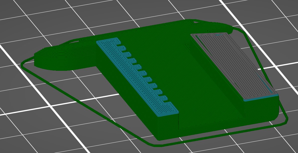
Printing the face plate
The face plate is a pretty straightforward print, which requires no intervention other than filament changes. There will be two color changes here, which will look like this:
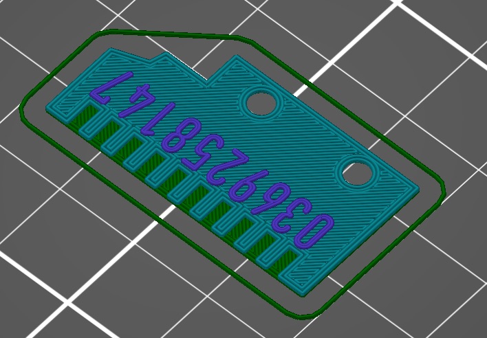
Start this print with black, then switch to orange, then switch back to black.
Printing the slider
You must print the face plate before the slider, because you’re going to insert the face plate mid-print.
This has a single filament and a pause, like so:
I’ve truncated the preview for this print right after the pause, so you can see where it happens. This is what the print will look like right before the pause:
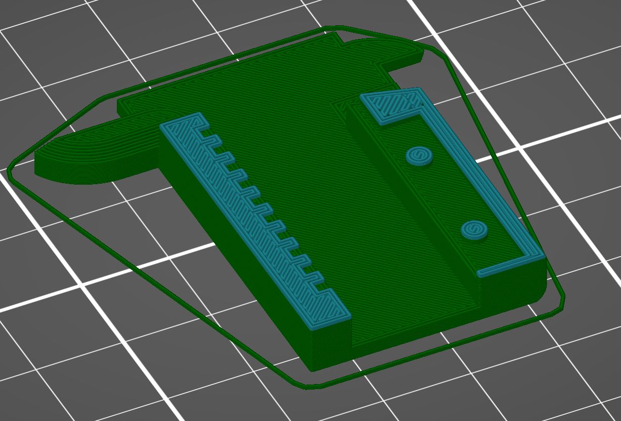
During this pause, you’re going to press the face plate into place, number side up, so that those pegs go through the holes in the plate. This does not have to be perfectly flush, but you need to get it as close as possible, and to have the plate sitting as close to horizontal as you can. Err on the side of having the plate hang low, rather than poking up.
(If your slicer/printer doesn’t support pausing, you can do a filament change here, and just put the same filament back in.)
For this print, start with black, then switch to orange.
Printing the body
The body is also a pretty simple print, with two color swaps:
Start with orange, switch to black, and then switch back to orange.
Final assembly
At this point, you should be able to simply slide the slider onto the body. The slider is retained by putting a keyring through the hole at the end of the body.
Now go grab a pair of proper calipers, and check that you’re getting the right values.